From Software to Hardware: Building My First Macropad

I’ve spent most of my career working as a software engineer. My tools are editors, terminals, browsers, and logs. Hardware, on the other hand, always felt a bit distant—interesting, but intimidating and opaque.
Recently, I decided to change that by building a small macropad from scratch. The goal wasn’t to design the perfect keyboard, but to understand the full journey: electronics, firmware, and finally software-level customization.
This post documents that process step by step, with the intention of making it easier for other beginners—especially those coming from a software background to try hardware without feeling overwhelmed.
Why a Macropad?
A macropad is a great first hardware project:
- The scope is intentionally small
- Each step gives immediate feedback
- Mistakes are cheap and recoverable
- You end up with something genuinely useful
Most importantly, the mechanical keyboard ecosystem has excellent tooling and documentation, which lowers the barrier to entry significantly.
Choosing a Microcontroller
The first decision was selecting a microcontroller. There are many options, but I wanted something:
- Inexpensive
- Easy to source
- Well supported by keyboard firmware
- Beginner friendly
I chose a Pro Micro–compatible board (ATmega32U4). It’s widely used in DIY keyboards, works well with QMK and Vial, and has native USB support—critical for keyboards. But there are a lot of clones available, so be sure to check reviews and community feedback before purchasing.
I want to keep my expenses low, as this is my first experience into hardware. So, i sources a clone board. I was skeptical about using a clone board at first, but it worked flawlessly throughout the project.

Link to the board i used.
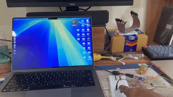
Setting Up the Arduino IDE and Testing the Board
Before wiring anything, I wanted to confirm that the microcontroller itself was working correctly.
I installed the Arduino IDE, connected the Pro Micro via USB, selected the appropriate board and port, and flashed a simple test sketch. Even something as basic as serial output or a blinking LED is enough here.
This step is important because it validates:
- The board is functional
- Drivers are installed correctly
- You can successfully flash firmware
Catching issues early saves a lot of frustration later.
void setup() {
  Serial.begin(9600);
  Serial.println("Pro Micro Test Started!");
}

void loop() {
  static int counter = 0;
  Serial.print("Counter: ");
  Serial.println(counter);
  counter++;
  delay(2000);
}
First Inputs: Reading Key Presses on a Breadboard
With the board working, I ordered a few mechanical switches and connected them using a breadboard.
At this stage:
- Each switch was wired directly to a pin
- No soldering was involved
- The logic was intentionally simple
Using the Arduino IDE’s serial monitor, I read key presses and printed values to the console. Pressing a physical switch and seeing output in software was a small but satisfying milestone.
We can use keyboard.hlibrary to send key presses over USB:
#include <Keyboard.h>
void setup() {
  pinMode(2, INPUT_PULLUP);
  Keyboard.begin();
}
void loop() {
  if (digitalRead(2) == LOW) {
    Keyboard.press('A');
    delay(100);
    Keyboard.releaseAll();
  }
}
In the above recording, you can see me pressing a key on the breadboard, which sends a series of keystrokes to the computer. Which opens spotlight and types brave and then presses enter to open the browser.
This phase helped me understand the basics of digital inputs without introducing too much complexity too early.
Discovering Matrix Wiring
Direct wiring works for testing, but it doesn’t scale.
I quickly ran into the limitation of IO pins and started looking into how real keyboards support dozens of keys with relatively small microcontrollers. That’s when I learned about matrix wiring.
In a matrix:
- Switches are arranged in rows and columns
- The firmware scans combinations instead of individual pins
- Far fewer IO pins are required
From a software perspective, this felt similar to replacing hardcoded logic with a proper data structure. One concept completely changed what was possible with the same hardware.
Here is a detailed explanation of matrix wiring for keyboards, that i used to learn more about from youtube
Learning to Solder and Adding Diodes
Once I understood matrix wiring, it was time to make the connections permanent. This also introduced a new concept that isn’t obvious at first: why diodes are necessary in a keyboard matrix.
When keys are connected in a matrix without diodes, pressing multiple keys at the same time can create unintended electrical paths. From the firmware’s point of view, this can look like extra keys are being pressed, even though they aren’t. This issue is commonly referred to as ghosting.
For example, pressing two keys in different rows and columns can allow current to flow through a third switch unintentionally, causing the firmware to register a phantom key press. This isn’t a bug in the firmware—it’s a limitation of the electrical design.
Diodes solve this problem by enforcing one-way current flow. By placing a diode in series with each switch, current can only travel in the intended direction, preventing these unwanted paths from forming. As a result:
- Ghost key presses are eliminated
- Multiple simultaneous key presses are handled correctly
- The firmware can reliably scan the matrix
Mechanical keyboards use 1N4148 signal diodes to prevent ghost key presses. These are the small orange glass diodes commonly seen in keyboard builds.
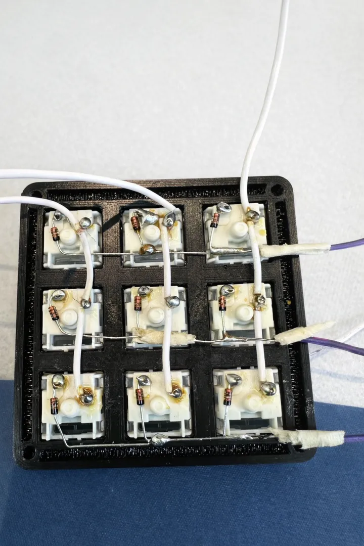
This was my first real experience with soldering. I practiced on spare wires, took things slowly, and focused on making clean, consistent joints.
Soldering the full matrix was one of the most hands-on parts of the project—and also one of the most rewarding.
Then i connected the the pro-micro back to my computed and tested all the keys again to make sure everything was working as expected. At this stage, we are still using the Arduino IDE to read key presses. And sketches for handling the matrix scanning. Each and every key press is hard-coded and mapped to a specific pin combination. So, if something needs to change, the firmware has to be updated and reflashed.
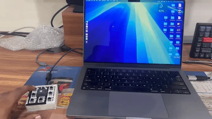
Printing the Case
At first, I was just searching for ready-made enclosures online, hoping to find something that would fit my layout. While there were some options, nothing quite matched what I wanted. That’s when I came across 3D printing.
Rather than designing a case from scratch, I found a suitable STL file on Printables that matched my layout and had it printed. This was my first real experience with 3D printing, and seeing the physical case for the first time was a turning point. Until then, the project felt like a collection of wires and components—once the printed case arrived, everything started to feel like a real, finished device.
Interestingly, this step also sparked my curiosity about 3D printing itself—materials, tolerances, and design possibilities—which is something I plan to explore more deeply in future posts.
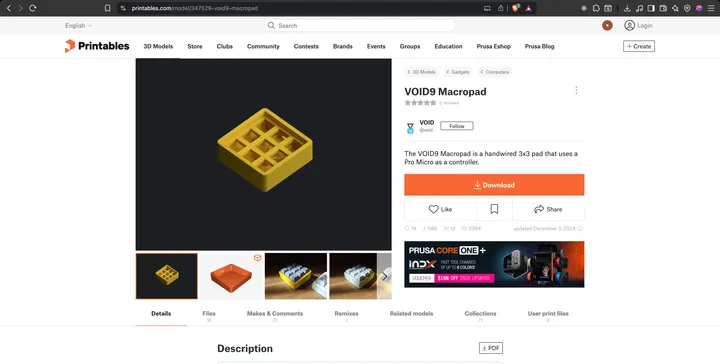
Link to the case design on Printables. I had the case 3D printed, and this was the moment when the project stopped feeling like a prototype and started feeling like a real device.
Moving from Arduino Sketches to Keyboard Firmware
Up to this point, I was still thinking in terms of Arduino sketches and pin-level logic. That changed when I discovered QMK and Vial, which allow for dynamic key mapping and much more flexible firmware.
At first, I struggled to find clear resources on using Vial with a custom macropad. Most guides assume existing keyboard designs, which made it tricky for beginners like me. After some searching, I came across a YouTube video that walked through the entire process of building a macropad with Vial support from scratch.
Following that video helped me understand the workflow, though I still ran into a few gotchas along the way. Those little challenges ended up being some of the best learning moments in the build process. Which i will document below.
These tools completely shift how you think about keyboard firmware:
- No need to hardcode pin handlers
- Key mappings are abstracted
- Layouts and behavior are configurable
- Changes can be made without rewriting firmware
- Building new macros was a lot easier
For someone coming from software, this felt like moving from bare-metal scripting to a proper framework. First we need to define the physical layout, then configure the firmware accordingly.
Designing the Keyboard Layout
To define the physical layout of the macropad, I used:
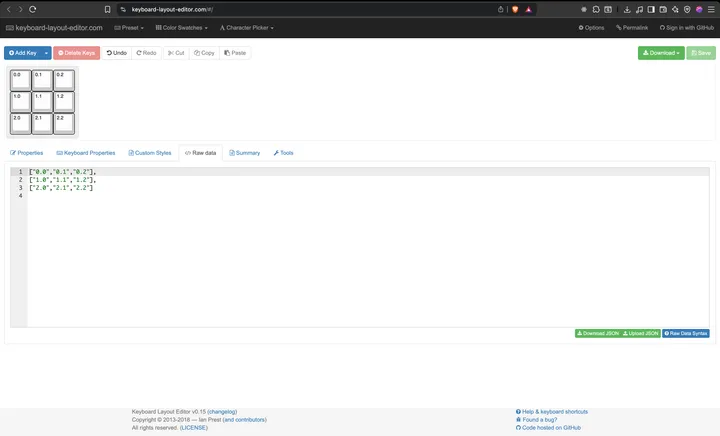
Keyboard Layout Editor. This tool lets you visually design the keyboard and export the layout as JSON. That JSON becomes the foundation for configuring QMK and Vial.
It’s an excellent bridge between physical design and firmware configuration.
Configuring Vial-QMK
To enable dynamic key remapping, I cloned the Vial-enabled QMK repository And followed the instructions to set up a custom keyboard configuration.
Inside the repository, I navigated to the keyboards directory and used an existing keyboard configuration as a reference.
I replaced the layout, matrix, and configuration files with my own setup. Here is a summry of the key files I modified:
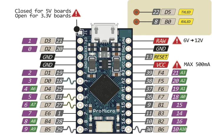
Remember all the pin connections we made earlier? This diagram was super helpful in mapping those physical pins to the matrix configuration in QMK.
// keyboards/3by2/config.h
#define MATRIX_ROW_PINS { C6, E6, B4 }
#define MATRIX_COL_PINS { D1, D0, D4 }
Find, the pin name from the diagram and replace it in the matrix row and column pins.
Next, for certain features inside vial, we need to setup a unlock combination. You can see this in later state in vial interface too.
#define VIAL_UNLOCK_COMBO_ROWS { 0, 1 }
#define VIAL_UNLOCK_COMBO_COLS { 0, 1 }
Next, I defined the layout macro to match my 3x3 key arrangement. I have a total of 9 keys arranged in 3 rows and 3 columns.
// keyboards/3by2/3by2.h
#define LAYOUT_h( K00, K01, K02, K03, K04, K05, K06, K07, K08 ) \
{ { K00, K01, K02 }, { K03, K04, K05 }, { K06, K07, K08 } }
Next, inside the vial.jsonfile, I specified the layout and matrix size to ensure Vial could interpret the key arrangement correctly.
Remember the JSON, that we downloaded from the previous step using the Keyboard Layout Editor?
// keyboards/3by2/keymaps/vial/vial.json
"matrix": {
  "rows": 3,
  "cols": 3
},
"layouts": {
  "keymap": [
    ["0,0","0,1","0,2"],
    ["1,0","1,1","1,2"],
    ["2,0","2,1","2,2"]
  ]
}
This helps Vial understand how to map physical keys to logical positions. And render the layout correctly in its interface. This part felt very familiar as a software engineer: reading existing code, understanding conventions, and adapting them for a new use case. Now, with the configuration in place, I was ready to compile the firmware.
For compiling the firmware, I used the following command from the root of the QMK repository:
qmk compile -kb 3by2 -km vialRunning this command generated a .hex file that could be flashed onto the Pro Micro.
Here is a link to the exact commit of my configuration changes for reference:
Flashing the Firmware
To flash the firmware onto the Pro Micro, I used QMK Toolbox, which is the most common and beginner-friendly tool for this step.
Once everything was wired and the firmware was compiled, the flashing process itself was fairly straightforward, but it still felt like a critical moment—this was where all the hardware and configuration work finally came together. The basic steps were:
- Connect the Pro Micro to the computer via USB
- Put the board into bootloader mode (this depends on the board and usually involves a reset action)
- Select the compiled
.hexfirmware file in QMK Toolbox - Flash the firmware onto the device
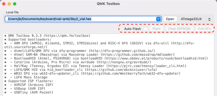
After flashing, the Pro Micro rebooted and was immediately recognized by the system as a USB keyboard. That was a reassuring moment—it confirmed that the wiring, firmware configuration, and flashing process were all working correctly.
If something goes wrong here, it’s usually recoverable, which made this step feel less risky than it initially seemed. Once the firmware flashed successfully, the macropad was officially alive.
Configuring Macros with Vial
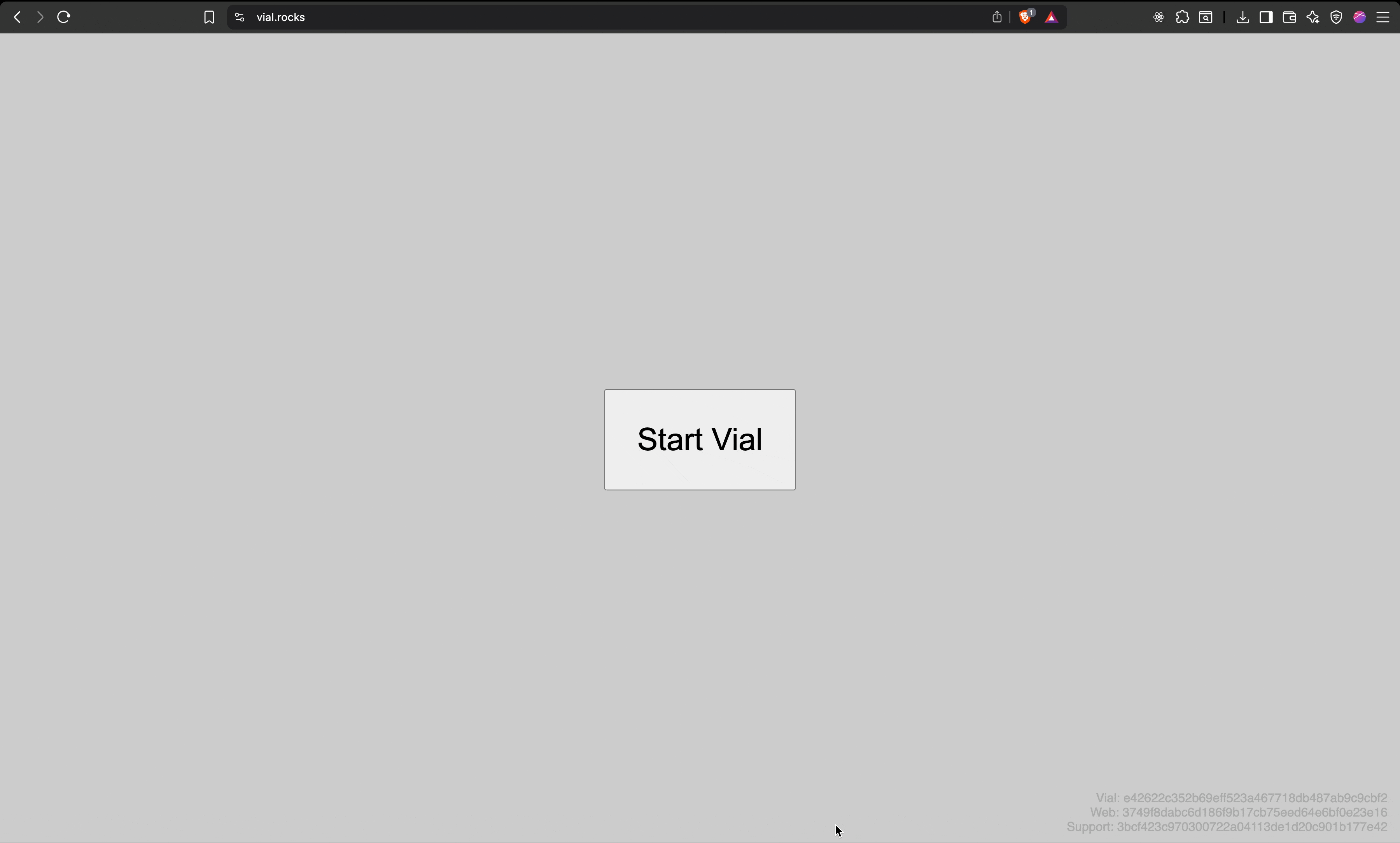
The final step was customization. Using https://vial.rocks/, I was able to:
- Detect the macropad automatically
- Remap keys in real time
- Add custom macros
- Experiment freely without reflashing firmware
This is where everything came together—hardware, firmware, and software working seamlessly.
What I Learned
Building this macropad made hardware feel far less intimidating than I expected. Once broken into small steps, each problem became approachable and even enjoyable to solve.
I was also surprised by how well software skills translated—especially when working with QMK and Vial. Much of it felt like configuring a framework rather than writing low-level firmware.
If you’re a software engineer curious about hardware, a macropad is a great place to start. The learning curve is real, but the feedback is immediate—and you end up with something you’ll actually use.